The Yagi-Uda Antenna: An Illustrated Primer
Baron Oldenburg August 26th, 2019 (Last Updated: August 26th, 2019)00. Introduction
As part of an upcoming project, I needed a quick and easy way to amplify the reception of a 428 MHz signal coming from a specific location. In antenna terms, I needed an antenna that gave me “high gain” (made the signal stronger) and was “highly directional” (only received signals from where I pointed my antenna). I needed it to be high gain because I’m not going to be directly next to the signal source and probably won’t have uninterrupted line of sight, and a high gain antenna allows me to be some combination of “far away” and “there are a lot of walls between me and the signal”. I needed it to be highly directional because I only care about the 428 MHz signal coming from my signal source and not any other random 428 MHz signals that happen to be where I’m pointing my antenna. 428 MHz is a pretty specific and non-standard wavelength for a directional antenna (i.e. it’s not WiFi) so it’s unlikely that I have one lying around (I didn’t) or that I would be able to buy one on the Internet (I couldn’t). Lucky day! I get to make a Yagi-Uda antenna!
01. What's a Yagi-Uda Antenna?
A Yagi-Uda antenna is a very easy to make high-gain highly-directional antenna. If you’ve ever seen a spindly antenna on top of someone’s house, it’s probably a Yagi-Uda!
Its ease of construction and the cheapness of materials combined with the amount of gain provided makes it an attractive option for DIY projects and prototypes.
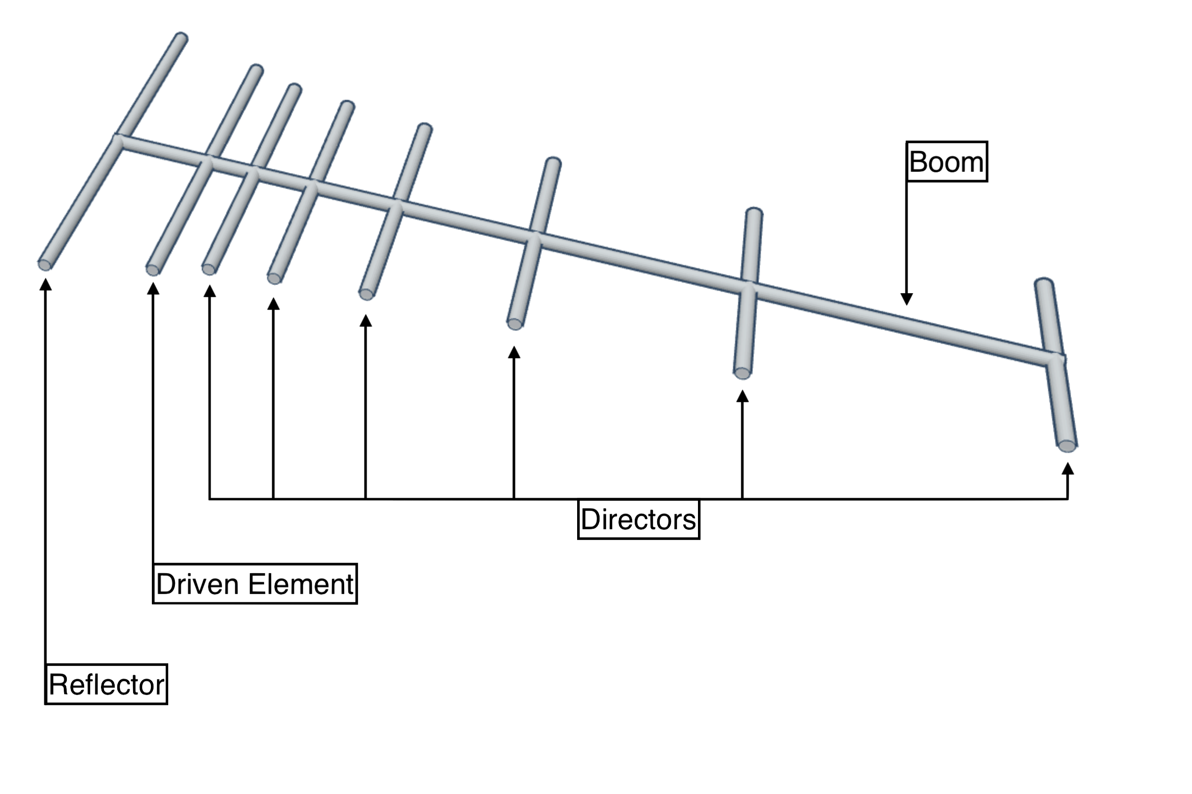
If you’re new to antenna building, there will be a lot of new terminology! Here’s a diagram:
Boom
This is the part of the antenna to which all the other elements are fastened. It can be conductive or non-conductive, its conductivity just affects the length of the other antenna parts. I used PVC pipe from Home Depot, so my boom was non-conductive.
Directors
These are the parasitic elements of the antenna. They modify the radiation pattern of the radio waves that hit them, re-radiating them with a different phase. This results in what is called “constructive interference”, which makes the overall signal stronger.
There are a lot of concepts and maybe some new words in that paragraph! Here’s a diagram to help illustrate:
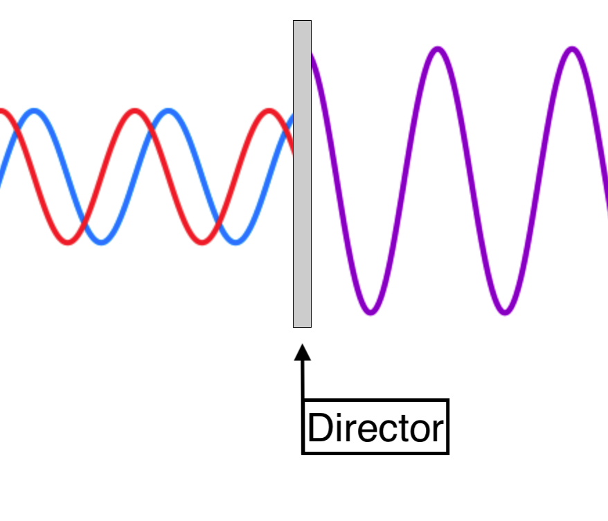
Here we can see two waves of the same wavelength (the red and the blue) hitting a director. These waves are offset from each other. Let’s say this director’s length is tuned to modify the phase of the red wave. We can see that after the red wave hits the director and is re-radiated, the two waves are now in phase and the resulting signal is stronger. The length of each director is such that it re-radiates waves that are at different phase offsets, aligning them all together for as much constructive interference as possible. This is why adding more directors also adds more gain to your antenna. Adding more directors also makes your beam more directional! You’ll also see directors referred to as “parasitics”.
Driven Element ("Dipole")
This is what radiates or receives the radio waves for the antenna. For me it’ll be receiving, and this is what the coax cable will be connected to. It has the directors on one side and the reflector on the other. As pictured above this is just a length of wire, but I decided to make a folded dipole, which looks like this:

Reflector
This is the longest piece of the antenna and sits opposite (“behind”) the driven element from the directors. This is considered the “rear” of the antenna and is part of what gives the antenna its directionality, by “blocking” waves coming from that side of the driven element. These reflectors can be more complex, like pictured on the TV antennas above, but for my purposes a single length of wire was fine.
02. How Do I Make One?
If you don’t have a lot of experience using antenna modeling software, you’re probably just going to go to the Internet and look for some calculators (and even if you do, you’ll probably still go to the Internet and look for some calculators). These calculators usually assume you’ve already built this kind of antenna in the past and spit out a list of measurements, which can be kind of intimidating for someone who doesn’t know what they’re doing. I’m going to walk through my build process, the calculators I used, and how to interpret the output of those calculators.
It’d been a few years since I built a Yagi-Uda antenna so I decided to start small and test that my principles were sound before starting on a bigger build. This initial prototype only had one director, a folded dipole, and a reflector, making it a three-element Yagi-Uda. I didn’t take pictures of the build process for this prototype, so some process shots will be staged and look slightly different from the final result.
03. The Prototype
A three-element Yagi-Uda is kind of an edge case so I used a calculator designed with that constraint in mind (https://www.changpuak.ch/electronics/yagi_uda_antenna.php). The output looked like this:
Frequency  :  428  MHz
Wavelength :  700.935  mm
d/lambda   :  0.006    ( min.: 0.001 , max.: 0.04 )
D/lambda   :  0.016    ( min.: 0.002 , max.: 0.04 )
Boomlength :  280  mm
Elements   :  3
Gain       :  7.1  dB    (approx.)
---------------------------------------------------
Reflector Length [mm] : 340
Reflector Position [mm] : 0
---------------------------------
Dipole Length [mm] : 338
Dipole Position [mm] : 140
---------------------------------
Director Length [mm] : 323
Director Position [mm] : 280
The parts we’re interested in here are the measurements for reflector length, reflector position, dipole position, director length, and director position. We won’t be using the dipole length because we’re going to make our own folded dipole.
Tools
- Measuring tape capable of measuring millimeters
- Wire cutters
- Drill press (or hand drill)
- Soldering iron
- (optional) 3d printer
Materials
- 4mm copper wire, at least 1500mm long
- PVC pipe, at least 300mm long
- Coax
- Solder
First
Cut the boom material to the length specified (280mm) + buffer (I used a buffer of 20mm for a total of 300mm).
I added 20mm here because you’ll notice that the reflector position is at 0mm and the director position is at 280mm so cutting a boom length of exactly 280mm wouldn’t be great. It’s also nice to have some wiggle room in case something goes wrong during fabrication.
Second
Mark the element positions.
For positioning the elements in the prototype I decided to do what I’ve seen a lot of other Yagi-Uda antenna builders do, which is to drill holes where the elements are supposed to go. This requires that you precisely measure where each element is positioned; tolerances are usually less than 2mm. All of the measurements we have for this prototype are relative to the reflector, so I marked 10mm from the end of the boom as the reflector’s location and added 10mm to each element’s position for measuring. Measuring from the end of the boom with a measuring tape is way easier and more consistent than trying to keep the end of your measuring tape hovering above a Sharpie mark on a PVC pipe.
Third
Drill holes for the elements.
It is important that all of the elements are:
- In line with each other (“coplanar”)
- Perpendicular to the boom
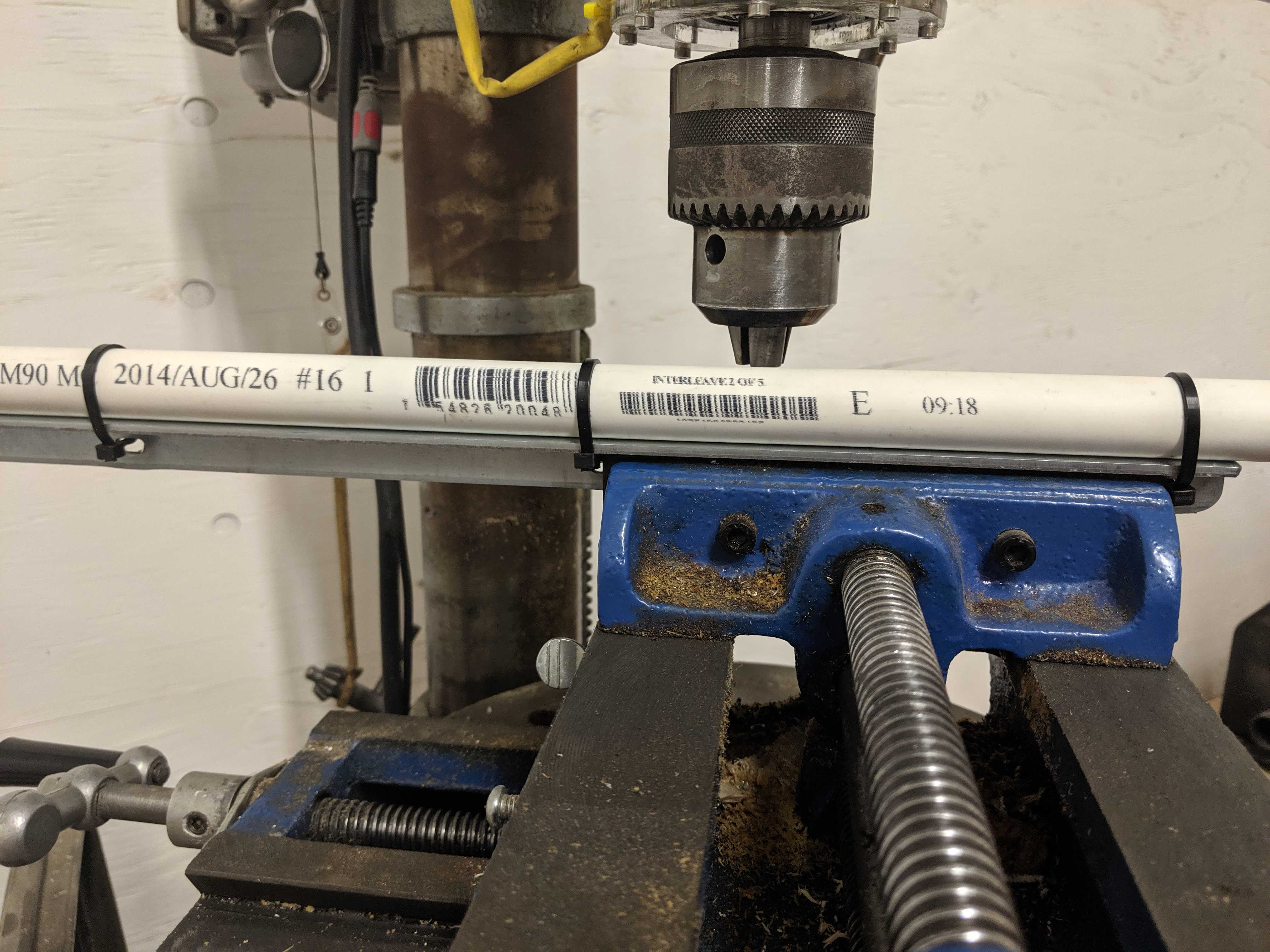
To these ends I zip-tied the boom to a spare piece of right-angle aluminum I had in the shop and clamped that in a vise. Using the aluminum and vise gave me a good guarantee for ##2, and using my shop’s drill press in combination with the aluminum/vise assembly instead of a hand drill gave me a good guarantee for ##1. Make sure the drill bit you use matches the diameter of your copper wire. Drilling too small a hole is okay because you can always make it bigger, but too big a hole will make your elements wobbly and it’s a harder fix.
Fourth
Measure and cut wire for elements.
For the reflector and director I used the measurements from the calculator above. Make sure as you’re cutting your elements you keep them in order! They only differ in length by a few millimeters.
Normally the reason that you’d choose to use a folded dipole instead of a half-wave dipole when constructing a Yagi-Uda antenna is to more easily match the impedance of the coax you’re attaching to it. While this is a nice property, it really only matters for antennas that also transmit, which we aren’t. I made a folded dipole instead of a half-wave dipole because it ends up being easier to attach to my boom and coax. Because I was creating my own folded dipole, I needed another calculator: https://www.changpuak.ch/electronics/Dipole_folded.php. The output from the calculator looked like this:
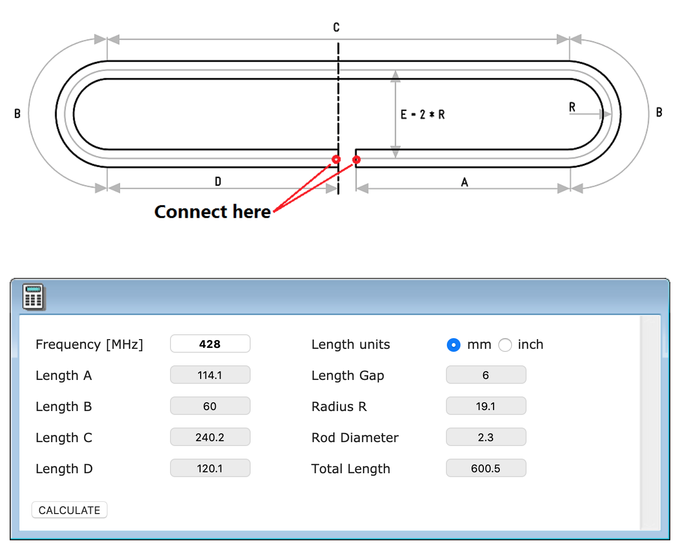
So we know the wire for our folded dipole needs to be 600.5mm long.
Fifth
Insert elements and bend the folded dipole.
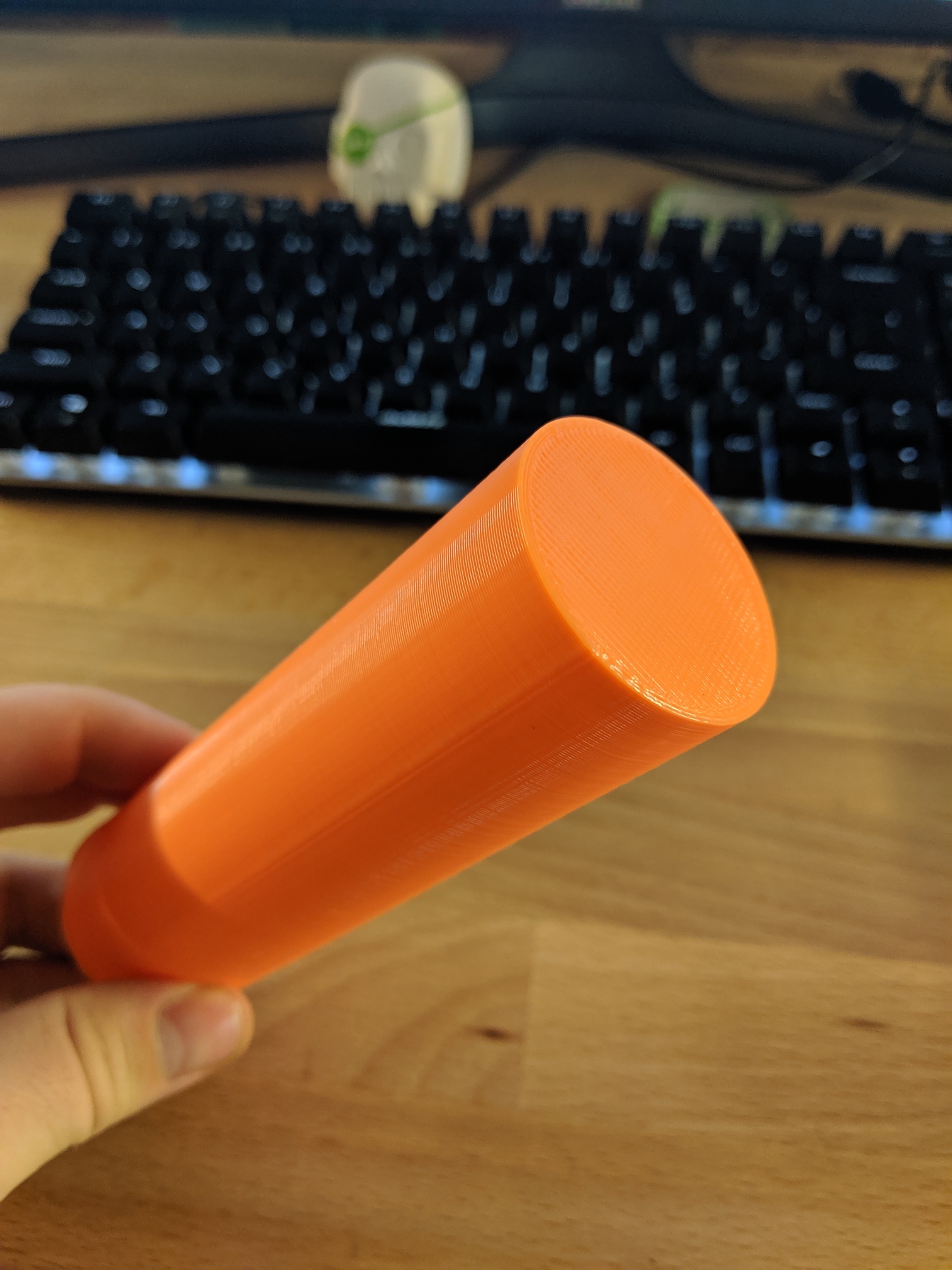
Inserting the reflector and director is straightforward. Bending the folded dipole, however, can be tricky depending on what gauge copper wire you’re using (thicker wire is more difficult to work with). I knew the radius of the bend and I had access to a 3d printer, so I printed a cylinder to use as a bend guide:
It’s important that all of the elements are centered on the boom, so I hot-glued each element in place. Some designs have the folded dipole in the same plane as the other elements, some designs have the folded dipole perpendicular to that plane, but from the antenna simulations I’ve seen it doesn’t matter so just pick whichever works for your antenna design or aesthetics.
Sixth
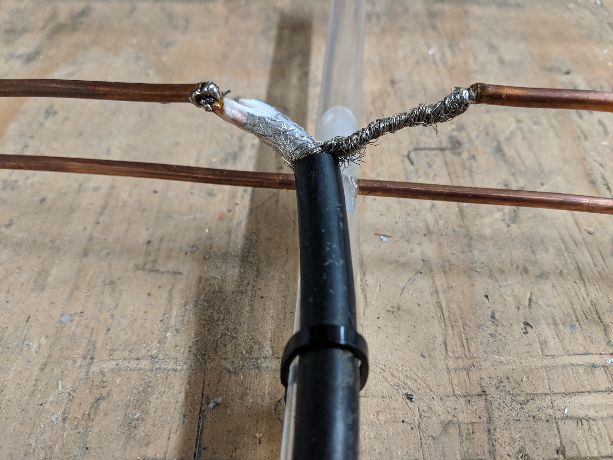
Solder the shielding of the coax to one end of the folded dipole and the copper core to the other.
Trim the plastic cover back from the coax a couple inches and pull the shielding off far enough so that the shielding reaches one side and the copper core reaches the other. As you can see below, I also zip-tied the coax to the boom to give the folded dipole some stability.
Prototype Complete!
Here’s a picture of my finished prototype:
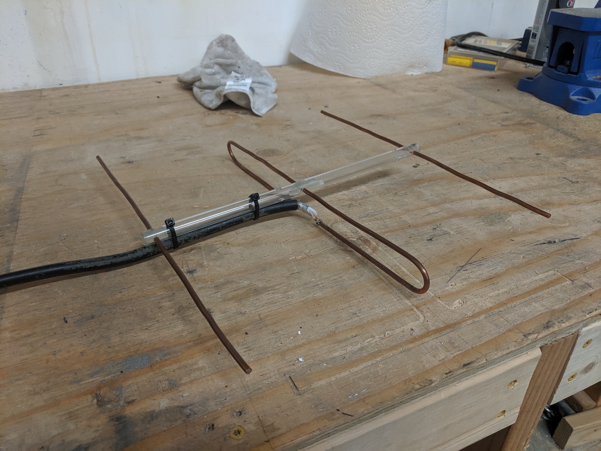
This antenna worked well enough to provide a 7dB gain at ten feet from the source, which was all I needed to confirm that a Yagi-Uda was a suitable antenna design for this project.
04. The Final Product
For the final product I made a 10-element Yagi-Uda antenna. I used a different calculator created for antennas with a variable number of elements: https://www.changpuak.ch/electronics/yagi_uda_antenna_DL6WU.php. These were my requirements:
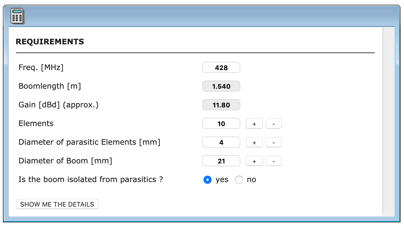
I had an eight foot length of white PVC pipe with a 21mm diameter from Home Depot that I planned to use for the boom, and Home Depot also sells fifteen foot rolls of 4mm copper wire.
The output of the calculator looked like this:
Frequency     :  428  MHz
Wavelength    :  701  mm
Rod Diameter  :  4  mm
Boom Diameter :  21  mm
Boom Length   :  1540  mm
d/lambda      :  0.006    ( min.: 0.002 , max.: 0.01 )
D/lambda      :  0.030    ( min.: 0.01 , max.: 0.05 )
Elements      :  10
Gain          :  11.80 dBd (approx.)
-------------------------------------------------------------
Reflector Length   : 338 mm
Reflector Position :  0 mm
-------------------------------------------------------------
Dipole Position    : 168 mm
-------------------------------------------------------------
Director #1 Position : 221 mm ,  Length : 319 mm
Distance Dipole - Dir. #1 : 53 mm
-------------------------------------------------------------
Director #2 Position : 347 mm ,  Length : 316 mm
Distance Dir. #1 - Dir. #2 : 126 mm
-------------------------------------------------------------
Director #3 Position : 498 mm ,  Length : 313 mm
Distance Dir. #2 - Dir. #3 : 151 mm
-------------------------------------------------------------
Director #4 Position : 673 mm ,  Length : 310 mm
Distance Dir. #3 - Dir. #4 : 175 mm
-------------------------------------------------------------
Director #5 Position : 869 mm ,  Length : 308 mm
Distance Dir. #4 - Dir. #5 : 196 mm
-------------------------------------------------------------
Director #6 Position : 1079 mm ,  Length : 306 mm
Distance Dir. #5 - Dir. #6 : 210 mm
-------------------------------------------------------------
Director #7 Position : 1300 mm ,  Length : 304 mm
Distance Dir. #6 - Dir. #7 : 221 mm
-------------------------------------------------------------
Director #8 Position : 1532 mm ,  Length : 302 mm
Distance Dir. #7 - Dir. #8 : 231 mm
This calculator has no dipole length because it assumes you’re making your own folded dipole. We are, so no worries there. Some steps of this build overlap with the prototype, so I’ll only make extensive notes where it deviates or there are new steps. The major change between the prototype and the finish build is that for the finish build I decided to 3d print standoffs for the elements instead of drilling holes in the boom. Drilling holes for the elements doesn’t scale well beyond a small antenna: there's very little room for error, small errors compound, a five foot length of PVC is way more unwieldy than one foot, and it’s difficult to make adjustments to elements after the hole is drilled.
First
Cut the boom material (remember to give yourself a buffer).
Second
Measure and cut wire for elements and folded dipole.
Third
Design and print element holder standoffs.
This is what I ended up with for my standoff design:
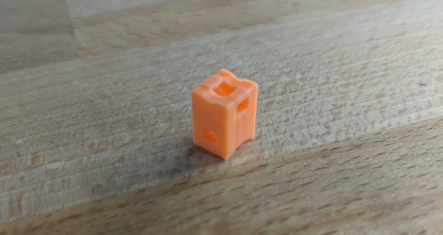
The curve on the bottom of the standoff matches the curve of the PVC pipe so the standoff sits nicely on the boom and doesn’t wiggle. The divot on top of the standoff matches the curve of the copper wire I used so the wire maintains its orientation. The holes in the side match the dimensions of the zip ties I used and the hole in the center is a design habit of minimizing solid volume to reduce the amount of filament used. For a piece this small (5mm x 5mm x 10mm) hollowing the core probably isn’t strictly necessary.
Using 3d-printed standoffs has a number of improvements over drilling holes:
- Easier to precisely position elements
- Easier to adjust elements if disturbed
- Easier to align elements to be coplanar
- Easier to replace or modify elements
- Easier to break down for transport, all you need to reassemble it is zip ties
- If the antenna gets bumped the elements don’t get bent
Fourth
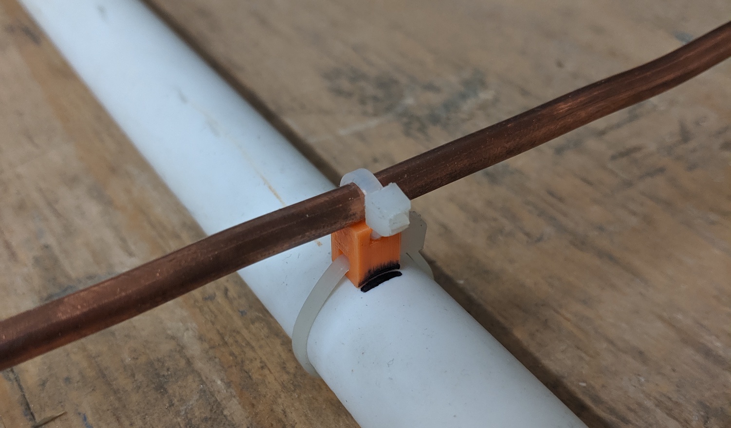
Zip-tie elements to standoffs and standoffs to boom.
Using the measurements from above, I zip-tied each standoff to the boom. With each element in place I re-measured to make sure it was within 1mm of the desired position, then marked the leading edge of the standoff with Sharpie so that if the antenna got jostled or an element got bumped I could easily reposition the standoff to the correct position.
Fifth
Solder the shielding of the coax to one end of the folded dipole and the copper core to the other.
Final Antenna Complete!
Here’s a shot of the final antenna minus the coax:

05. Conclusion
Building your own custom-tuned antennas isn’t that difficult! The hardest part is knowing where to start and how to interpret the output of the calculators you find online. Hopefully through learning about how the antenna works, seeing my build process, and learning some of the gotchas I encountered along the way you feel confident that you can do this at home.
06. Resources Used
3-element Yagi-Uda calculator
https://www.changpuak.ch/electronics/yagi_uda_antenna.php
N-element Yagi-Uda calculator
https://www.changpuak.ch/electronics/yagi_uda_antenna_DL6WU.php
Folded dipole calculator
https://www.changpuak.ch/electronics/Dipole_folded.php
